EPC diagram
EPC diagram, short for event-driven process chain diagram, is a flowchart based diagram that can be used for resource planning and identifying possible improvements of a business process.
EPC diagram could contain the following elements :
- Event
- Function
- AND, OR or XOR operators
- Organisation Unit
- Control Flow
- Process Path
- Organization Unit Assignment
- Information Resource
- Information Flow
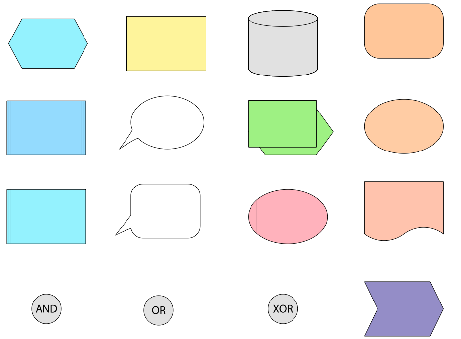
All of these elements could be found in EPC diagram library.
![]() 16 objects
16 objects
Event
Events are passive elements in event-driven process chains. They describe under what circumstances a function or a process works or which state a function or a process results in. Examples of events are “requirement captured”, “material in stock”, etc. In the EPC graph an event is represented as hexagon. In general, an EPC diagram must start with an event and end with an event.
Function
Functions are active elements in an EPC. They model the tasks or activities within the company. Functions describe transformations from an initial state to a resulting state. If different resulting states can occur, the selection of the respective resulting state can be modeled explicitly as a decision function using logical connectors. Functions can be refined into another EPC. In this case it is called a hierarchical function. Examples of functions are “capture requirement”, “check material in stock”, etc. In the event-driven process chain graph a function is represented as rounded rectangle.
Process owner
Process owner is responsible for a function (i.e. a booking clerk is responsible for booking journeys). The process owner is usually part of an organization unit (i.e. a booking clerk belongs to the booking department). It is represented as a square with a vertical line.
Organization unit
Organization units determine which organization within the structure of an enterprise is responsible for a specific function. Examples are “sales department”, “procurement department”, etc. It is represented as an ellipse with a vertical line.
Information, material, or resource object
In the event-driven process chain, the information, material, or resource objects portray objects in the real world, for example business objects, entities, etc., which can be input data serving as the basis for a function, or output data produced by a function. Examples are “material”, “order”, etc. In the EPC graph such an object is represented as rectangle.
Logical connector
In the event-driven process chain the logical relationships between elements in the control flow, that is, events and functions are described by logical connectors. With the help of logical connectors it is possible to split the control flow from one flow to two or more flows and to synchronize the control flow from two or more flows to one flow.
Logical relationships
There are three kinds of logical relationships defined in event-driven process chains:
Branch/Merge: Branch and merge correspond to making decision of which path to choose among several control flows. A branch may have one incoming control flow and two or more outgoing control flows. When the condition is fulfilled, a branch activates exactly only one of the outgoing control flows and deactivates the others. The counterpart of a branch is a merge. A merge may have two or more incoming flows and one outgoing control flow. A merge synchronizes an activated and the deactivated alternatives. The control will then be passed to the next element after the merge. A branch in the EPC is represented by an opening XOR, whereas a merge is represented as a closing XOR connectors.
Fork/Join : Fork and join correspond to activating all paths in the control flow concurrently. A fork may have one incoming control flow and two or more outgoing control flows. When the condition is fulfilled, a fork activates all of the outgoing control flows in parallel. A join may have two or more incoming control flows and one outgoing control flow. A join synchronizes all activated incoming control flows. In the Event-driven Process Chain diagram how the concurrency achieved is not a matter. In reality the concurrency can be achieved by true parallelism or by virtual concurrency achieved by interleaving. A fork in the EPC is represented by an opening ‘AND’, whereas a join is represented as a closing ‘AND’ connectors.
OR : An ‘OR’ relationship corresponds to activating one or more paths among control flows. An opening ‘OR’ connector may have one incoming control flow and two or more outgoing control flows. When the condition is fulfilled, an opening ‘OR’ connector activates one or more control flows and deactivates the rest of them. The counterpart of this is the closing ‘OR’ connector. When at least one of the incoming control flows is activated, the closing ‘OR’ connector will pass the control to the next element after it.
Control flow
A control flow connects events with functions, process paths, or logical connectors creating chronological sequence and logical interdependencies between them. A control flow is represented as a dashed arrow.
Information flow
Information flows show the connection between functions and input or output data, upon which the function reads changes or writes.
Organization unit assignment
Organization unit assignments show the connection between an organization unit and the function it is responsible for.
Process path
Process paths serve as navigation aid in the EPC. They show the connection from or to other processes. The process path is represented as a compound symbol composed of a function symbol superimposed upon an event symbol. To employ the process path symbol in an Event-driven Process Chain diagram, a symbol is connected to the process path symbol, indicating that the process diagrammed incorporates the entirety of a second process which, for diagrammatic simplicity, is represented by a single symbol.
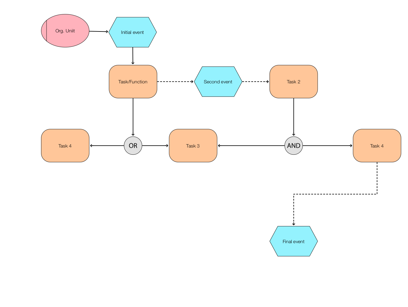
Example diagram: